So I was updating my resume today and noticed I never posted our final video here on the blog. In this video we show that the car is actually correctly following the way-points we define. This project did get finished in time for our senior design deadline, and we even took our professor for a ride in the car to demonstrate (which he was very excited about). I have heard that the car is now likely to be used for PhD students to conduct research with so hopefully we’ll get to see it do even more autonomous driving in the future.
Autonomous Driving!
Today was a good day. We are now able to autonomously follow a path of waypoints defined by our app. As usual here is a video:
For this video we made a zig-zag pattern across the parking lot. We will have future videos with different paths. In the end I will try to even include the path in the video so you can see the intended route.
Now despite what it would seem from my lack of updates, we did not in fact jump right from simulations to autonomous driving. There was alot of work to be done getting the board to communicate with the realtime linux computer (we ended up revamping our serial communication 3 or 4 times) and to get obstacle detection working. In addition to the autonomous path following we have also implemented autonomous braking for obstacles as seen in this video:
The autonomous braking took much of our time over the past weeks as it required that we have good obstacle detection, stable communication and reliable control of the car. In all there was a lot that has been missed by this blog, the mounting of the LIDARs with metal mounts Austin welded up, reading speed from the velocity encoder, two new PID loops for setting the command steering position and the velocity, and dealing with EMF issues.
This is however the most important milestone. We hope to have a test that integrates these two features within the next week. We will then focus on getting the project cleaned up into a final product that can be used for future research and demos.
Filed under Uncategorized
Path Planning
Once again I have taken forever to update this, but once again a lot has been done since the last post!
The biggest update I have for you is that over the break I managed to write some path following and path planning simulations that we will use as a basis for the code to be written this quarter.
The first stage of implementation will be to simply follow a path and stop if we see any obstacles. This will allow us to ensure that our object detection and path following algorithms are working and give us a chance to calibrate our PID values for the path following algorithm.
The path following will look like this:
In this simulation I compute what is called the cross track error to use as the error for my PID controller that determines the steering angle. The cross track error is basically the length of a line from the vehicle to the path that perpendicularly intersects the path.
From here we will move on to actually mapping the obstacles and planning paths to avoid the obstacles.
In this simulation the waypoints are marked by blue dots. The empty black circles mark obstacles. They become filled in red once they are discovered by the car. The car uses a modified A* search algorithm to find a path to the goal and recomputes the path from its location whenever it discovers a new obstacle.
In addition we have some other updates:
Realtime Linux:
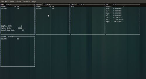
We have been working on getting the Linux computer setup to have the interface with everything working under the Linux realtime task scheduler. Working off an example given to us by Dr. Jay Farrell at UCR we were able to get setup pretty quickly. We have the interface to the Fez Panda II and the GPS all set up and are in the process of getting the LIDAR to interface with it. It has a nice simple display interface that looks like this:
Note: This screenshot was taken without anything connected which is why the GPS values are off.
PCB Testing:
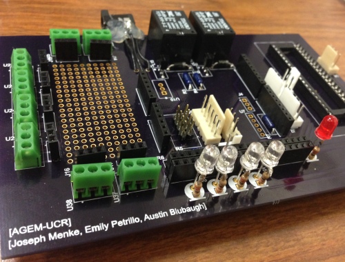
The PCB has now been fully populated and looks like this:
I have been going through and testing the individual interfaces to the car. There have been some minor errors, the most interesting being that the magnetic field caused by the relays turning on was pulling the 5v pin away from connecting with the female header on the Panda II and so the relays never finished turning on. It was a simple fix (I just coated the pin with a layer of solder so it was thicker and made a better connection to the header) but it was a very interesting time trying to figure out the problem. We ended up doing a continuity test between the Panda II and the PCB (which in theory should have always shown connected) but sure enough it would become unconnected whenever we tried to turn the relay on.
Overall though we have been able to work out any errors with simple fixes and we should have the the hardware finalized within the next week.
Filed under Uncategorized
IT DRIVES!!!
I (Joe) have been quite busy and unable to make posts lately, but that does not mean there hasn’t been progress. Last week we took the car out for it’s first official test drive!
There were however some bugs in the initial code:
But after a few bug fixes we were able to get it driving quite well:
There are some things we needed to do to get it working that I haven’t talked about yet:
Throttle:
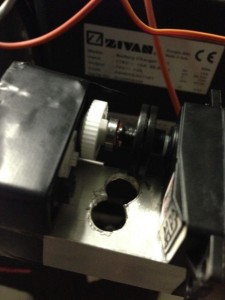
The digital potentiometer did not end up working out. We are still not entirely sure why but the chips seemed extremely fragile and would heat up quickly despite us supplying voltage that was fully withing specs (and quadruple checking all our connections). In the end we ended up replacing it with a mechanical solution:
For this I took two servos and removed the motor from one, only using the potentiometer. I also broke out the potentiometer on the working servo so we could get feedback on its position. In the end this proved to react a little slower than we wanted so I will be replacing it with a high-speed servo that will increase the speed 3x.
Steering:
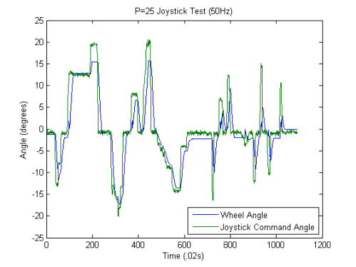
As we can only control the speed of the steering motor and not directly control the position it was necessary to write a PID controller to get it to go to a specified position. For now we only calibrated the P term but we will be calibrating for the integral term as soon as we have the tires pumped (the tires being low on air is affecting our ability to actually turn the wheels).
Here is our response to a commanded position with our control algorithm running at 50Hz:
(Thanks to Austin for making the nice graph)
PCB:
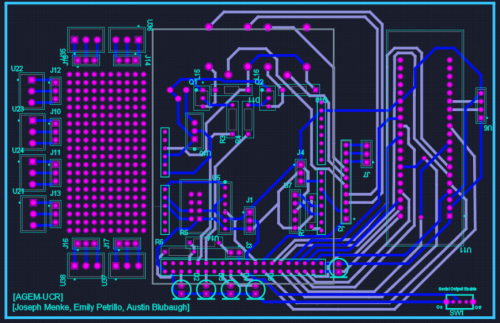
Now that we had the car running the next step is to make a PCB. We have finished the design and will be ordering it in the next couple days:
We decided to add a prototyping area on the side with screw terminals in case we needed to add any additional unforseen items to our board. This allows for secure mounting with a good amount of flexibility in our design.
Our next steps are to finalize hardware and move on to remote control of the vehicle 🙂
Filed under Uncategorized
Throttle and New Microcontroller
Testing the throttle:
This week it was time to test if the car could actually move. According to the documentation all that was needed was to simulate a -5 to +10v signal to the throttle signal pin. The schematic in the service manual showed what appeared to be a potentiometer used as a voltage divider for the gas pedal. This made sense and was what I expected the gas pedal to be. What was interesting though was that the high and low voltages actually changed depending on vehicle activity. With nothing connected it showed a 5v difference. After connecting a gas pedal I removed from our spare GEM vehicle, there was a -3v difference. This was probably the reason behind the choice of using a digital potentiometer vs a DtoA converter.
Even with the gas pedal from the other car we had some difficulty getting it to move. It turns out that the car has a neutral position which corresponds to neither the forward nor reverse wires being connected. It took us moving all our batteries to the spare GEM to find this, but once we had everything moved back we were able to move our GEM just fine with the gas pedal.
While I was testing this Emily was setting up the circuit for the digital potentiometer. This involved setting up the +-15V DCtoDC converter and getting SPI working to set the potentiometer value from the Arduino. However upon connecting power to the circuit it began to smoke and she realized she had incorrectly connected power to the potentiometer.
Replacing the potentiometer:
Needing to replace the potentiometer we looked online to see if we could find a DIP version that would be easier to test. While DIP versions of potentiometers are quite common, ones that can handle +-15V are not. In the end we decided we would have to get an SMD version. Not wanting to wait to get a breakout board made I decided I was going to make one myself. We decided on the AD7376 in the 16-SOIC package. This decision was made because it has very similar functionality to the previous potentiometer with the difference that this one came in a larger package that would be easier to make a board for.
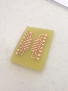
I decided that since I needed to make a board anyway I was going to make it into a workshop for my fellow IEEE members and senior design students in case anyone else ran into a similar problem. About 10 students showed up to the workshop. I taught the toner transfer – acid etching method of making PCB’s. I really like this method because it doesn’t require any special equipment (besides a common clothing iron) and it actually turns out pretty good results.
Here is the finished board:
The New Microcontroller:
Austin has been hard at work porting all of our code to the new microcontroller, the Fez Panda II. He got turning and auto centering ported very quickly. From there we worked out getting the break system working (we ended up hooking up a function generator to the controller) and he implemented that in code (a 200-300 hz signal with a 25% duty cycle). This was interesting because all of the PWM ports are attached to the same timer and thus must all have the same period. In the end he used a software pwm to implement this.
Getting the quadrature decoder to work with this microcontroller was a little more difficult. You will recall that the decoder requires a high frequency clock signal. Unlike the arduino we could not simply set a fuse to have this output its clock signal. We looked on the internet for methods on how to implement a clock signal. The consensus we got was that you could only do this with software interrupts (outside of the pwm ports) and for a fast enough signal this was just not feasible. Having worked with ARM processors before, I wasn’t willing to accept that this was the only way. I knew that ARM microcontrollers normally have pins that you can set to toggle on match with a timer counter. So I looked up the datasheet and found that you can do exactly this. It took some reading to get the registers right but eventually I was able to figure it out and Austin was able to implement it on our microcontroller. Sure enough we were able to get an 18MHz signal to output from our microcontroller. Perfect for our quadrature decoder.
For anyone who is interested the register configuration to get an 18Mhz signal on DO33 is as follows:
Register T2IR = new Register(0xE0070000);
T2IR.Write(0);
Register T2CR = new Register(0xE0070004);
T2CR.Write(1);
Register PCONP = new Register(0xE01FC0C4);
PCONP.SetBits(1 << 22);
Register T2CTCR = new Register(0xE0070070);
T1CTCR.Write(0);
Register T2PR = new Register(0xE007000C);
T1PR.Write(0);
Register MR0 = new Register(0xE0070018);
MR1.Write(1);
Register T2MCR = new Register(0xE0070014);
T1MCR.Write(2);
Register T2EMR = new Register(0xE007003C);
T1EMR.Write(0x0030);
Register PINSEL9 = new Register(0xE002C024);
PINSEL9.Write(0x02000000);
Register PCLOCK_SEL_1 = new Register(0xE01FC1AC);
PCLOCK_SEL_1.SetBits(1 << 12);
PCLOCK_SEL_1.ClearBits(1 << 13);
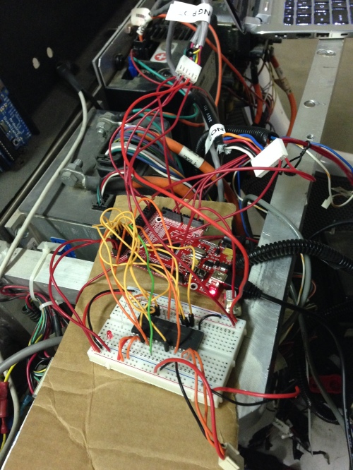
The wiring was a little crazy but Austin got it set up and working:
Needless to say the final product will have a PCB for connecting all components together,
Filed under Uncategorized
Last Week: Steering Calibration and Batteries
Since the last blog post a lot has happened. Here is some of what we have been working on:
Steering Calibration:
One big accomplishment last week was that we got the automated calibration of steering setup. The vehicle has three sensors for steering: A quadrature encoder, a 10k potentiometer, and a homing sensor. The quadrature encoder is a high resolution encoder that provides an accurate representation of the steering position. The only problem with it is that it does not retain its count when it loses power. This means that in order to have an accurate position representation from the encoder we need to first center it. To make this happen, a homing sensor was placed at the center position of the steering shaft. This sensor consists of and IR Led and IR transistor, and a screw that passes between them when the shaft is in the center position. The reading from the IR transistor can then be attached to an interrupt pin on the microcontroller to trigger it to reset the quadrature encoder. The potentiometer is used to get an initial reading of the motor’s position so that we know what direction to turn in order to get to center. What we accomplished was that on startup the vehicle will now automatically center itself and reset the quadrature encoder. Emily and I (Joe) worked on getting the code for this working.
Batteries!
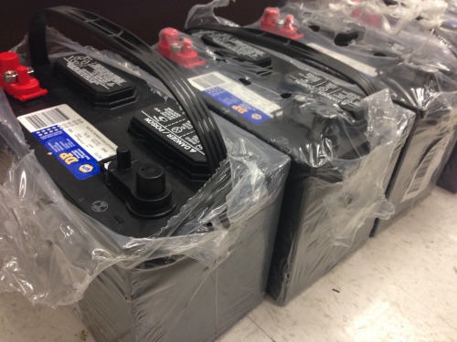
So in addition to the batteries we needed for the 12v and 24v systems in the car we also needed the main batteries for a 72v system that the original motor and electronics in the car run’s off of. I looked at several different methods if getting batteries. The one that ended up working out was a company called Napa Auto Parts in Riverside (Awesome company, amazing people, thank you guys so much!). After contacting TAPS (Transportation And Parking Services) at UCR and asking where they buy their batteries from I was directed to this company. I called them up and basically asked if there was any way we could get batteries donated and they agreed! I picked up six batteries from them of Thursday of last week and we installed them in the car on Friday. They are 12v flooded lead acid batteries for Marine/RV. They are compatible with the onboard charger in the GEM vehicle making them perfect for our needs.
GPS
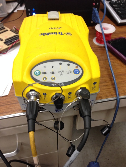
Last week we also began working with a Trimble GPS unit. I did the initial setup, which consisted of finding the programs, installing them on linux, and getting the unit to output data over the serial port on startup. I then turned it over to Emily so she could work with the linux program and write code to parse the GPS NMEA messages.
Brake Controller and Remote:
While Emily worked with the GPS I setup the 12v system in the car and tested the Brake Controller. It was wired to go to full power when one of the buttons was pressed on a keychain remote. This seemed to be the easiest test and worked beautifully. Pressing the button caused the brake controller to activate and stopped the car from moving.
Additionally there are three more buttons on the remote that activate relays on a remote control board that had been added to the car. The documentation stated that one of the buttons was intended to be used as a way to switch between autonomous mode and manual mode. Upon closer inspection however I realized that this was no longer wired correctly (the wire was simply tied to ground). I rewired it and tested that the button now made the wire switch between 0v and 5v (It did).
New Microcontroller:
This week we realized we would not have enough pins on our Arduino for what we needed. We debated purchasing an Arduino Mega for the increased pinout but instead we found a board that had previously been purchased for the car but had never been installed. It is an arm based board with an Arduino Mega form factor. It runs at 72Mhz and is programmed in C#. Austin took on the task of porting all of our code over to this microcontroller as he is very familiar with C#.
Filed under Uncategorized
Base Station Joystick
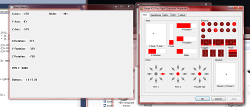
Over the course of a few days, I (Austin) began working on writing a C++ program to read a USB Joystick. I used Microsoft’s DirectX SDK because it seemed to provide the most versatility between different joysticks as well as having fairly decent documentation to go with it. The program itself is still a very rough draft, but it is able to read all the important values on the Joystick (Axis locations, and button presses). The program then copies all those values into a byte array that gets transmitter over a TCP/IP socket to a receiver program. The whole purpose of doing this is so that after the car is running by manual control (with a person physically in the car), we can implement manual control from the base station. The purpose of doing this is so that while the car is driving autonomously and something goes wrong, we should be able to immediately take manual control from the base station.
Below is a picture of the C++ joystick reader program (on the left) and the actual values from Windows (on the right):
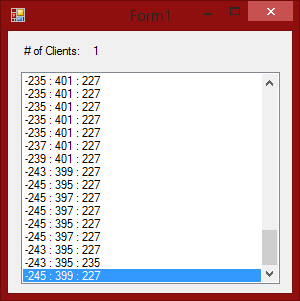
And below is a picture of a demo receiver program that was running on my laptop and connected to the primary program over Wi-Fi.
In the picture below the numbers represent the joystick X-axis, Y-axis, and Z-axis.
Later in the project, this receiver program (or something very similar) will be running on the vehicle’s on board computer. This setup will allow us to take control of the car at any time should something go wrong. It also allows us to monitor the connection between the car and the base station so that if the connection is lost at any point, the on board computer will immediately know about it and stop the car.
Filed under Uncategorized
Steering Works!!
The past couple days we have been working on getting the steering up and running.
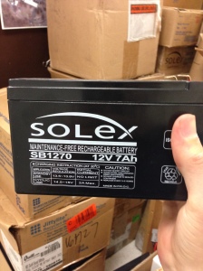
We got a large donation of batteries to CECERT that will be used for our project, various research projects, and even distributed to other senior design groups (I know we made several senior design groups very happy with this).
These batteries will be used for 12v and 24v systems on our car and they have allowed us to begin testing the steering motor.
We started with a test to make sure that the motor worked and determined the correct signal to make it move (pwm signal at 15625 Hz, 25% duty cycle is do nothing, 20% move left at full speed, 30% move right at full speed). From there we split up to separate tasks. Emily worked on code for getting the min, max and center values for the steering potentiometer as well as the range of values output from the joystick while I (Joe) worked on getting the quadrature decoder setup correctly.
When we actually went to run these tests we ran into some issues. The biggest was that while trying to test the min and max potentiometer values we blew out a fuse by trying to move the motor too fast when it could not turn any more. At first we did not realize that this was the issue. We simply lost power to the motor driver and, while my first inclination was that we had blown a fuse, I checked the 24v system fuse and it was fine. So we assumed the problem was with the motor driver. We removed the motor driver and tested it separately and it worked fine. Then looking for another cause for the problem we discovered that there was a separate fuse just for the motor that had blown. We replaced the fuse and verified that the cause of the problem by blowing the fuse again (semi-accidentally). After replacing the fuse yet again we were able to get everything working and get the data that we needed.
In the meantime Austin has been working on (very successfully) getting a joystick to transmit over wifi for our remote control and getting the SICK lidar set up and writing all the code to read and interpret data from it. I’ll try to get him to post about it in the next couple days.
On our next work day we hope to get the steering calibration sequence working (it has to center itself on startup, will be described next time), as well as get our 24v battery system finalized with charging, mounting, and anything else that needs to be done.
Filed under Uncategorized
Testing Sensors
In our last work day Emily and I (Joe) wrote code for the Arduino to interface with each of the sensors that have been added to the car. We proceeded to test these sensors to ensure that they were all still working.
Most of the sensors proved pretty simple:
-The steering potentiometer was connected to an analog pin on the Arduino. It provides a 0-5V signal depending on the position of the wheels. We still need to test to find the leftmost, rightmost, and center values. We didn’t have a floor jack on that day so this test would have been pretty difficult.
-The centering sensor was connected to an interrupt pin on the Arduino and set up to trigger when the pin goes high. We managed to turn the wheels enough to get it to trigger correctly.
-The velocity encoder was connected to the remaining interrupt pin and we checked that the count was incremented when the wheels turned. Still need to verify that it reports the correct number of ticks per revolution, but again we needed a floor jack for this.
One sensor however was more complicated:
-The quadrature encoder for the steering motor is quite high resolution and a quadrature decoder chip is used to interpret the signal coming from it. We considered removing this chip and processing it solely on the Arduino but due to the resolution (meaning it would take alot of the Arduino’s computation time) and the fact that we would need two interrupt pins to read it, we decided it would be best to keep the chip. The problem with this is that the chip requires an external clock source and the Arduino does not normally output it’s clock. I looked into using several different methods of generating a clock signal. While we may eventually end up making a clock signal from a 33Mhz oscillator, I found we could output the clock signal from the Arduino by setting the CKOUT fuse on the ATMega328p. This is simple enough to do with an AVRISP and Atmel Studio. The fuse has been set and I tested the signal on an oscilloscope but the final sensor still needs to be tested.
Filed under Uncategorized
Understanding Wiring and Control
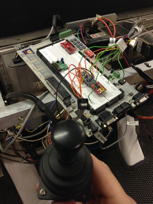
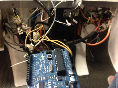
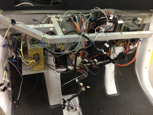
For this work day Emily and I (Joe) went through all the wiring in the car to understand what everything did. This was done by going through the wiring diagram in the service manual in conjunction with the description of what had been added in the documentation we were given. We labeled everything as we went so not to forget what everything did. It may look like a mess (even after we zip tied things and cleaned it up) but it is really not so bad once you understand it all.
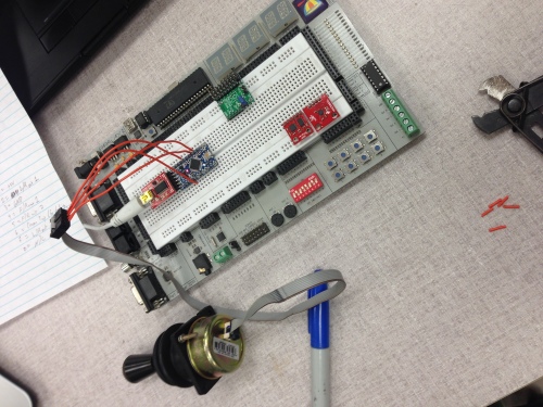
In the meantime Austin took the Joystick from the car and got it to interface with the Arduino. We decided to keep the joystick control for drive by wire as long as it is working (which it is).
This leads into what we will be doing our next work day which is to test all the sensors on the car and write code to interface with them in Arduino.
Filed under Uncategorized

